
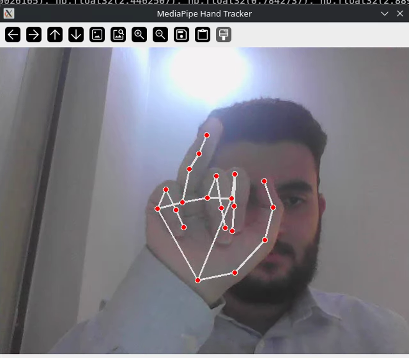
Every vision-driven robotics project has a moment where the camera stops being a camera and starts being a sensor. For this one, that moment is MediaPipe Hands: a webcam frame goes in, and 21 numbered points in space come out.
It is easy to treat that as a black box. It is also a mistake, because the box has a specific shape, and its failure modes follow directly from how it was built.
It is two networks, not one #
The single most useful thing to know about MediaPipe Hands is that it is a cascade: a detector and a regressor, with completely different jobs.
flowchart TB
    A["📷 Full frame
e.g. 640 × 480"] --> B["Stage 1 — BlazePalm
SSD detector"]
    B --> C["Oriented palm crop
256 × 256"]
    C --> D["Stage 2 — Landmark regressor
MobileNetV2-style encoder"]
    D --> E["63 floats
21 landmarks × (x, y, z)"]
    D --> F["Presence score"]
    D --> G["Handedness
left / right"]
    F -->|"confidence ≥ 0.5"| C
    F -->|"confidence < 0.5"| B
Stage 1 — BlazePalm detects palms, never fingers #
This is the design decision the whole system rests on.
Detecting fingers is expensive. They articulate through enormous ranges, they occlude one another constantly, and their apparent shape varies wildly with pose. Detecting a palm is cheap, because a palm is close to a rigid body — roughly rectangular, and its bounding box stays coherent whatever the fingers are doing.
So BlazePalm is a Single Shot Detector trained to find the oriented bounding box of the palm and nothing else. It uses a MobileNetV3-like feature extractor with an encoder-decoder (FPN-style) structure, which preserves high-resolution context so a hand can be found whether it occupies 10% or 100% of the frame.
Its failure mode is specific and reproducible. Point your hand directly at the camera so the fingers hide the palm, and tracking drops — not because the fingers are confusing, but because the thing the detector actually looks for is no longer visible.
Stage 2 — the regressor never sees the frame #
The landmark model receives only the cropped, rotation-normalized 256×256 palm tensor. It has no idea what else is in the image.
It is a pure regression network — a MobileNetV2-style encoder using inverted residuals and linear bottlenecks, aggressively downsampling through strided depthwise separable convolutions into a dense feature map, then splitting into task-specific heads:
| Head | Output | Trained with |
|---|---|---|
| 2D landmarks | 21 × \((x, y)\) | MSE on manually annotated real images |
| Depth | 21 × \(z\) | L2 loss, almost entirely on synthetic 3D hands |
| Presence | Is a hand actually in this crop? | Binary cross-entropy |
| Handedness | Left or right | Binary cross-entropy |
Two ideas that make it fast #
Depthwise separable convolutions #
A standard convolution mixes spatial and channel information in one expensive operation. The depthwise separable version splits it: a \(3 \times 3\) spatial convolution applied independently per input channel, then a \(1 \times 1\) pointwise convolution to combine channels linearly.
The result is the same class of feature at a small fraction of the multiply-accumulates, which is what allows real-time high-resolution scanning without a GPU.
Focal loss, because the background wins by default #
A webcam frame generates thousands of candidate anchor boxes. One or two contain a palm. Under standard cross-entropy, the gradient signal is swamped by the overwhelming mass of easy negatives — the network learns “this is background” extremely well and learns nothing useful about hands.
Focal loss fixes the imbalance by down-weighting confident predictions:
$$FL(p_t) = -\alpha_t (1 - p_t)^\gamma \log(p_t)$$The modulating factor \((1 - p_t)^\gamma\) collapses toward zero when the network is already sure. Gradient updates therefore concentrate on the genuinely hard cases — distinguishing a hand from a forearm, or from a face.
The z-axis is an educated guess #
Your webcam has no depth sensor. MediaPipe reports a \(z\) coordinate anyway.
It is inferred, not measured. The depth head is trained on synthetic 3D hands where exact geometry is known, it anchors the origin \((0,0,0)\) at the wrist (landmark 0), and it learns to read relative depth from apparent scale, shading and occlusion. As the perceived 2D spread of the fingers shrinks, the network concludes the hand is further away.
This is relative depth, not metric depth. You cannot convert it to centimetres.
For this project that turns out not to matter at all, and the reason is worth internalizing: the kinematics downstream only ever computes angles between vectors, and an angle is invariant to uniform scaling of the coordinate system. A systematically compressed or stretched \(z\) axis shifts every vector consistently, and the angle between two of them survives. Had the pipeline needed absolute fingertip positions, none of this would work.
The tracking loop — why stage 1 almost never runs #
MediaPipe hits 30+ FPS on a CPU because it usually skips half of itself.
- Frame 1 — BlazePalm scans the whole image, finds the palm, hands the crop to the regressor.
- Frame 2 — BlazePalm is skipped entirely. The pipeline assumes the hand has not moved much, expands the previous bounding box by a margin, and feeds that straight to the regressor.
- Repeat until the presence score drops below the confidence threshold — fast motion, an occlusion, a hand leaving frame. Only then is the cache flushed and the detector woken.
In this project’s node, that threshold is set explicitly:
self.hands = mp_hands.Hands(
    static_image_mode=False,
    max_num_hands=1,
    min_detection_confidence=0.5,
    min_tracking_confidence=0.5,
)
static_image_mode=False is what enables the loop at all — set it True and the detector runs on
every single frame, which is correct for photographs and disastrous for video.
The two thresholds are a genuine tradeoff. Raise them and the detector re-engages more eagerly: more robust to drift, more expensive, more dropouts. Lower them and the pipeline clings to a tracked hand longer — smoother, cheaper, and prone to confidently tracking something that is no longer there.
Two APIs, and this project uses the older one #
Worth knowing before you copy code between MediaPipe examples, because they are not interchangeable.
| Legacy Solutions API | Modern Tasks API | |
|---|---|---|
| Import | mp.solutions.hands |
mediapipe.tasks.python.vision |
| Model | Bundled in the pip wheel | Downloaded .task file |
| Input | Raw NumPy array | mp.Image wrapper |
| Landmarks | results.multi_hand_landmarks |
detection_result.hand_landmarks |
| Handedness | Parallel multi_handedness |
Parallel handedness array |
The ROS node uses the Solutions API — deprecated upstream, still shipped, and simpler for a single fixed-configuration pipeline. The standalone demos use the Tasks API, which is the supported path forward and gives finer control over the confidence thresholds.
Landmark indices are identical across both. Landmark 4 is the thumb tip either way.
The jitter problem, and the 1€ filter #
Here is the failure mode nobody warns you about: hold your hand perfectly still, and the landmarks do not.
The regressor outputs sub-pixel coordinates with no temporal constraint whatsoever. Each frame is an independent estimate, so consecutive frames disagree slightly. Your hand is motionless; the numbers quiver.
The naive fix is a low-pass filter, and it fails in an instructive way. A standard first-order filter,
$$\hat{x}_i = \alpha x_i + (1 - \alpha)\hat{x}_{i-1}$$has one constant \(\alpha\) governing everything. Set it low enough to kill the jitter and fast motion visibly lags. Set it high enough to track fast motion and the jitter comes back. One knob cannot serve both, because they are opposite requirements.
The 1€ filter resolves this by making the cutoff frequency depend on speed:
$$f_c = f_{c,\min} + \beta \lvert \dot{x} \rvert$$When your hand is nearly stationary, \(\lvert\dot{x}\rvert \approx 0\), the cutoff collapses to \(f_{c,\min}\), heavy smoothing engages, and the signal locks in place. When you move quickly, the velocity term drives \(f_c\) up, filtering drops toward nothing, and lag disappears.
The smoothing factor is derived from the sampling period \(T_e\) and the time constant \(\tau = \frac{1}{2\pi f_c}\):
$$\alpha = \frac{1}{1 + \frac{\tau}{T_e}}$$and the filter runs in two stages per sample: estimate the velocity and smooth it at a fixed 1 Hz cutoff, then use that stable speed estimate to set the dynamic cutoff for the position.
def filter(self, t, x):
    t_e = t - self.t_prev
    if t_e <= 0.0:
        return self.x_prev
    rate = 1.0 / t_e

    # 1. estimate and smooth the velocity
    dx = (x - self.x_prev) / t_e
    alpha_d = self._alpha(rate, self.d_cutoff)
    dx_hat = alpha_d * dx + (1.0 - alpha_d) * self.dx_prev

    # 2. dynamic cutoff from that velocity, then filter the position
    cutoff = self.min_cutoff + self.beta * abs(dx_hat)
    alpha = self._alpha(rate, cutoff)
    x_hat = alpha * x + (1.0 - alpha) * self.x_prev

    self.x_prev, self.dx_prev, self.t_prev = x_hat, dx_hat, t
    return x_hat
Two knobs, each with an unambiguous job:
min_cutoff— lower it if the signal still quivers when you hold still.beta— raise it if fast motion still lags.
This is not yet wired into the robotic hand. The ROS node applies no smoothing at all; raw
angles go straight through the mapping and out to /joint_states. The jitter is partly masked
because publishing at 10 Hz subsamples the noise, and because a rotating mesh is a far more
forgiving output than a mouse cursor. It remains the single highest-value upgrade available to the
pipeline, and a working implementation already sits in the demo folder waiting to be lifted.
Four demos, four techniques #
Each of the standalone scripts in the repository isolates one idea, runnable in ten seconds without Docker, ROS 2 or a URDF.
Virtual-Air-Canvas.py — a gesture is a state transition, not a pose. Draws a trail from your
fingertip, but only while thumb and index are pinched. The pinch test is a normalized Euclidean
distance against a threshold, which makes it scale-invariant: the same threshold works whether your
hand fills the frame or sits in a corner.
system-brightness-sound-control-demo.py — handedness and continuous mapping. Left hand
controls volume, right controls brightness, both by the thumb–index gap. Two lessons: handedness
arrives in a parallel array indexed alongside the landmarks, and it is only correct if you mirror
the frame first, because MediaPipe labels hands from the camera’s point of view. It also
rate-limits with a deadband, because spawning a pactl subprocess thirty times a second locks up
the desktop.
hand-mouse.py — the 1€ filter under real load. A complete virtual mouse with press/release
state so dragging works. Run it once with the filter bypassed to feel exactly how unusable raw
landmarks are for anything demanding precision.
cool-animation.py — landmarks as arbitrary geometry. Four fingertips from two hands become
the corners of a quadrilateral acting as an AR window into a second image. The instructive bug it
solves: four points arrive in landmark order, not spatial order, and filling a polygon with
mis-ordered vertices produces a bowtie. The fix is sorting by angle about the centroid.
What you should take away #
- It is two networks, and the detector’s palm-only design explains its main failure mode.
- The \(z\) axis is inferred, and relative depth is enough for angle-based work and useless for metric work.
- The tracking loop is why it is fast, and the confidence thresholds are the dial that trades robustness against cost.
- Raw landmarks jitter, always. Plan for filtering before you plan for precision.
Next: what those 21 points become once you start treating them as a mechanism.