
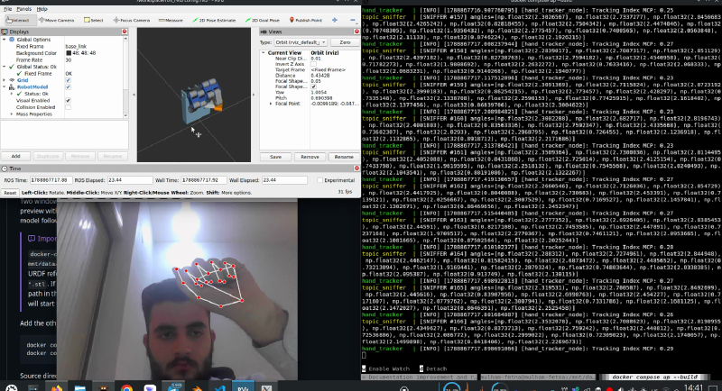
You hold your hand up to a laptop camera. On the other half of the screen, a robotic hand — designed in CAD, never manufactured — closes its fingers at the same moment yours do.
There is no glove, no marker, no depth sensor. Just an RGB webcam, two small neural networks, about forty lines of vector geometry, and a middleware stack that thinks it is talking to a real robot.
All of it is open source under AGPL-3.0 and archived with a DOI: 10.5281/zenodo.22658556.
flowchart LR
    A["📷 Webcam
/dev/video0"] --> B["BlazePalm
palm detector"]
    B --> C["Landmark regressor
21 × (x, y, z)"]
    C --> D["Dot-product geometry
15 interior angles"]
    D --> E["Normalize → flexion
0.0 straight · 1.0 curled"]
    E --> F["Lerp onto the URDF's
mechanical limits"]
    F --> G["/joint_states"]
    G --> H["robot_state_publisher
→ /tf"]
    H --> I["🖥️ RViz digital twin"]
The rule that shaped the build #
There is an easier version of this project. Collect a few thousand frames of a hand next to the corresponding CAD poses, train a network to map one to the other, and let gradient descent work out the relationship.
I did not build that, on purpose. Every number in this pipeline is derivable by hand.
That constraint costs accuracy — a learned mapping would handle the thumb’s compound rotation far better than linear interpolation does. What it buys is diagnosis. When the ring finger moves wrongly, there is exactly one arithmetic path from three camera coordinates to a radian value in the URDF, and you can walk it. In a learned system, the same symptom is a shrug and a request for more data.
That matters here because this model is meant to eventually drive physical servos. A twin you cannot debug is a twin you cannot trust with hardware.
Stage 1 — 21 points from a flat image #
MediaPipe Hands is not one network but two, cascaded.
BlazePalm scans the full frame looking only for the rigid bounding box of the palm — never fingers. Fingers articulate, occlude each other, and vary wildly in shape; palms are stubbornly rectangular. Detecting the easy thing and cropping to it is what makes the pipeline fast enough for a CPU.
The landmark regressor then ignores the frame entirely and sees only that crop, emitting 63 continuous floats: 21 landmarks × \(x, y, z\).
The clever part is that stage 1 almost never runs. Once a hand is found, the next frame reuses the previous bounding box with a small margin and goes straight to the regressor. The detector only wakes when confidence drops — a fast movement, an occlusion, a hand leaving frame. That temporal shortcut is the whole reason this runs on a laptop.
The \(z\) axis is worth being honest about: a webcam has no depth sensor, and MediaPipe fakes it. The network was trained on synthetic 3D hands, anchors \(z=0\) at the wrist, and infers relative depth from apparent scale and shading. It is relative, not metric — which turns out to be sufficient, because the kinematics that follow only ever measure angles between vectors, and angles are invariant to the overall scale of the coordinate system.
Stage 2 — from points to angles #
Here is the hinge of the entire project, and it is just trigonometry.
To measure a joint, take three adjacent landmarks: the joint itself as the vertex, plus its two neighbours. For the index finger’s PIP joint that is landmarks 5, 6 and 7. Build two vectors radiating out from the vertex along the bones:
$$\vec{v}_1 = P_1 - P_2 \qquad \vec{v}_2 = P_3 - P_2$$and recover the interior angle between them from the dot product:
$$\theta = \arccos\left(\frac{\vec{v}_1 \cdot \vec{v}_2}{\lVert\vec{v}_1\rVert \, \lVert\vec{v}_2\rVert}\right)$$Fifteen triplets, fifteen angles, no state, no learning. A straight finger reads about 3.10 rad (≈177°); a curled one about 1.60 rad (≈90°).
Two numerical traps live in that one line, and both bit during development. If MediaPipe emits two
identical landmark coordinates, a bone length is zero and the division produces NaN. And
floating-point error routinely pushes the cosine to 1.0000000002, which is outside \(\arccos\)’s
domain and raises. The guards are unglamorous and non-optional:
if norm1 < 1e-6 or norm2 < 1e-6:
    angles.append(0.0)
else:
    cosang = np.clip(np.dot(v1, v2) / (norm1 * norm2), -1.0, 1.0)
    angles.append(float(np.arccos(cosang)))
Stage 3 — from human angles to mechanical ones #
A raw angle is a biometric measurement. A URDF joint has mechanical limits that came out of CAD. Bridging them takes two steps.
Normalize the raw angle into a flexion ratio between fully open and fully curled:
$$\text{flexion} = \frac{\text{RAW\_STRAIGHT} - \theta}{\text{RAW\_STRAIGHT} - \text{RAW\_CURLED}}$$Interpolate that ratio onto the joint’s actual range:
$$\theta_{\text{urdf}} = \theta_{\text{open}} + \text{flexion} \times (\theta_{\text{closed}} - \theta_{\text{open}})$$RAW_STRAIGHT_ANGLE = 3.10 and RAW_CURLED_ANGLE = 1.60 are the calibration window — empirical
constants, not derived ones. They define which slice of human motion gets stretched across the
mechanism’s full travel, and they are the first thing to touch when the whole hand under- or
over-flexes.
The per-joint limits come from the URDF itself, parsed at startup. A fifteen-row table binds each computed angle to a named joint and records which end of its range is the open hand:
JOINT_MAPPING = [
    ('thumb_mcp',   0, 'lower'),
    ('index_mcp',   3, 'upper'),
    ('middle_pip',  7, 'lower'),
    ...
]
Note the open end disagrees between rows: thumb_mcp opens at its lower limit, index_mcp at its
upper. That is not sloppiness — it reflects how each mate was constructed in CAD, and it is the
only per-joint fact the table still stores. The angles themselves are read from the URDF.
Stage 4 — publishing into a robot #
The tracker publishes two topics per frame, and the split is deliberate:
| Topic | Type | Contents | Purpose |
|---|---|---|---|
/hand/joint_angles |
hand_msgs/JointAngles |
15 raw radians | Telemetry — the vision layer in isolation |
/joint_states |
sensor_msgs/JointState |
15 named, mapped joints | Drives the twin |
That redundancy pays for itself the first time something looks wrong. Compare the two streams and the fault localizes immediately: bad raw angles mean a vision problem, good raw angles with bad mapped ones mean a table problem.
One deliberate omission is worth calling out. Standard ROS 2 URDF demos run a
joint_state_publisher that invents joint positions from GUI sliders. This project deletes it.
The tracker is the joint state publisher. Leaving both running would put two publishers on one
topic, and the model would flicker between your hand and whatever the sliders last held.
Stage 5 — where the model came from #
The hand was designed in Onshape — the assembly is
public
— and exported with onshape-to-robot, which reads mate names, mate limits and material densities
straight out of the CAD. Done properly, that means joint names
and inertia tensors are generated rather than hand-written.
Done improperly, every shortcut taken in CAD becomes a bug in ROS. This export produced a good one — real inertias from 1.86 g at the fingertips to 61 g at the palm, every revolute axis correctly on local Z — and three defects that are documented rather than hidden.
The most memorable: duplicating a finger sub-assembly in Onshape copies its mates and their
names, so the ring finger arrived carrying the pinky’s twinky_mcp. Two joints with one name; the
exporter dropped one; the ring finger had no base knuckle.
And yes — twinky. A legacy name for the pinky, still in the CAD, therefore in the URDF,
therefore in the Python mapping, because JointState matches joints by exact string.
Stage 6 — making it run anywhere #
ROS 2 Jazzy is hard-locked to Ubuntu 24.04, which is a good reason to containerize. But robotics containers are a strange exercise: you isolate the process, then spend your time punching holes back through the isolation for the webcam, the GPU, the display server and the network.
Four services, all on network_mode: host because DDS discovery uses UDP multicast and a Docker
bridge network kills it; /tmp/.X11-unix mounted so RViz has a portal to your monitor;
/dev/video0 and /dev/dri passed through for the camera and hardware rendering; source
directories bind-mounted so a code change needs a restart, not a three-minute rebuild.
What it does not do #
Four honest limits, each a documented next step rather than a hidden flaw:
flowchart TB
    A["✅ Working today
vision · kinematics · TF · RViz twin"] --> B["⬜ No smoothing
landmark jitter passes straight through"]
    A --> C["⬜ No physics
Gazebo spawns the model,
nothing drives it"]
    A --> D["⬜ No actuation
no transmissions, no controllers, no servos"]
    A --> E["⬜ Forward kinematics only
per joint, no IK, no coupling"]
There was also, until recently, a live defect worth recounting. Fourteen of the fifteen mapping
rows transcribed their joint’s limits exactly. ring_mcp carried 0.000 / -1.571 against a URDF
limit of 0.39671 / -1.17409 — a leftover from before that mate gained a real limit in CAD. At
full curl the node commanded roughly 23° past the joint’s mechanical stop.
Nothing errored. robot_state_publisher does not enforce URDF limits; it applies whatever
transform it is handed. So RViz showed a ring knuckle bending slightly further than the mechanism
physically could, silently — and it would have become a hard failure the moment this drove a
physics engine or a real servo.
The row is fixed — but the class of bug is the part worth keeping: a contract duplicated across two files, with no mechanism to detect divergence.
So the duplication went away. The limits are now parsed from the URDF when the node starts, and the
Python table holds only which end of each joint’s range is the open hand — the one fact a
<limit> element cannot express. Editing the CAD no longer requires editing Python, and a joint
renamed by a re-export raises at startup rather than silently freezing a finger.
The same shape still sits in the duplicated hand_msgs package, where a field added to one copy
and not the other yields a subscriber that silently never fires. Worth knowing where your second
copies are.
What it was actually for #
This is a first ROS 2 project, not a novel result, and the pitch should say so. Markerless hand teleoperation is well-trodden ground.
What makes it worth writing up is the integration. Computer vision, hand-derived kinematics, a CAD-to-URDF pipeline with real material properties, an industry-standard middleware, and a reproducible containerized environment — connected end to end, by one person, with the failures documented rather than cropped out of the demo video.
The gap between “I can train a model” and “I can make a model, a mechanism and a middleware agree with each other in real time” is most of the job in robotics. This is a small, complete instance of that gap being closed.
The code, all six documentation chapters and the DOI are on GitHub.